Friday, July 24, 2020

Two-Tier Collapsed Core Architecture

Two-Tier Collapsed Core Architecture

With the purpose to minimize the cost of devices and deployment while maintaining most of the benefits of the three-tier hierarchical internetworking model, the core layer and the distribution layer are collapsed into one layer, implementing the functions of two layers in a single device. Such type of design is called “collapsed core”. Reducing the three layers to two layers makes it possible to ease the burden of management and also makes it easier to troubleshoot network performance problems of the fewer hardware devices. Generally, the two-tier internetworking model is seen in the small-sized enterprise networks in which there are fewer than 200 users.
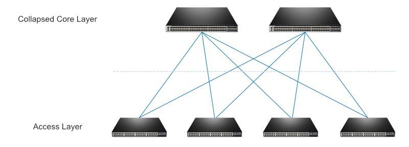
Figure 1 Two-tier collapsed core architecture.jpg

Figure 1: Two-tier collapsed core architecture

Distribution Switches in Three-Tier Architecture

In mid-sized to large enterprises comprising over 200 users, two-tier architecture is no longer available for the high requirement of network performance and availability. The traditional three-tier hierarchical network design comes to the stage and plays its role.

Figure 2 Distribution layer in a three-tier architecture.jpg

Figure 2: Distribution layer in a three-tier architecture

In the three-tier hierarchical network design, the distribution layer switches connect the core layer and access layer in an enterprise, functioning as a bridge so all the traffic to and from the access layer can flow into high-bandwidth trunk ports, and then the data is smoothly transmitted to the core layer for routing to its final destination. Besides the role of the connection point of the multiple access switches, distribution switches also play the role of terminating VLANs from the access switches, summarizing routing to access layer and so on.

Overall, whether to use the three-tier enterprise network architecture or two-tier collapsed core architecture depends on the type of the network and the potential future scale. If you are to build midsize and large enterprise networks with a larger amount of users, the two-tier collapsed core design is not a well designed one. Considering the cost and management, it is common to use two-tier design in a small-sized business network, but one cannot rule out the high potential to grow in size. In this case, network designers should take potential growth into account for future requirements. If network growth is possible, the three-tier enterprise network architecture is recommended.

Factors to Consider When Choosing Distribution Switches

No matter in two-tier collapsed or three-tier enterprise network architecture, you should make it clear what functions you require for the distribution switches in the collapsed core layer or distribution layer. With the general factors such as port type, port density and port speed considered, the following section will focus on the switch forwarding rate and functions that the distribution layer requires. Here are the factors for reference.

Layer 3 Function

It is always the responsibility of distribution switches to process Layer 3 data. The traffic generated from the access layer devices needs to be segmented into VLANs, requiring the upper-class switches to provide inter-VLAN routing functions so as to enable the multiple VLANs to communicate with each other. Since the core layer has a heavy task to handle the forwarding of the extremely high volumes of traffic, distribution switches with Layer 3 functionality are deployed to ease the workload of the core switches.

Forwarding Rate

The forwarding rate embodies the processing capabilities of a switch in the form of the data number that a switch process per second. It is a critical factor to consider when choosing a distribution switch. It is often the case that the forwarding rate of distribution switches is higher than the access switches. If the packet forwarding rate is too low, the distribution switch will not accommodate full wire-speed communication.

Redundancy

Redundancy is an important issue to consider for distribution switches. It is suggested that distribution switches should support multiple and hot swapping power supplies so as to achieve higher availability. With the redundant power supplies, the distribution switches can still operate normally without affecting the network traffic even if one power supply fails. In the meantime, the power supply can be replaced with a new one while the other one keeps operating as usual.

Link Aggregation

To forward all the traffic generated from the access layer to the core layer as fast as possible, distribution switches should support link aggregation so as to increase the network performance by keeping the traffic among a bunch of links balanced. Another key feature to use link aggregation is when a failure occurs, link aggregation will provide quick recovery. Generally speaking, link aggregation is an essential factor to take into consideration, which both increases availability and provides redundancy.

Security Policy

Security policy needs to be employed on the distribution layer switches to prevent promiscuous traffic through the network and allow others to go through. With the use of security policies such as access control list (ACL), the distribution switches can identify which types of traffic are permitted to communicate and which does not match the ACL rules defined on the switch ensuring the security of the whole enterprise network.

QoS Capacity

Setting up an intelligent QoS is essential for effective network capacity. As so many users sending traffic of various types within the LAN, deploying distribution switches with QoS features will read packets and prioritize delivery based on the policies so as to enable the important traffic to go first. It will ensure the audio and video data communicate in an adequate bandwidth. FS S5800-48F4S switches are well suited to the role of enterprise distribution switches supporting QoS capacities to improve the network traffic performance.


Monday, March 18, 2019

Cisco IOS Configuration Mistakes

Cisco IOS Configuration Mistakes You May Commonly Make
1. Password Verification
One easily made mistake comes with the way that passwords are configured with IOS. Unlike almost every other password configuration tool available, the password commands on IOS do not confirm the password being entered. Imagine getting a new piece of equipment configured and put into the field, then later when remote management is required, attempting to access the device only to learn that the password was entered incorrectly. In most cases, the only way to fix this is to have you or someone else physically on-site. Take care when configuring IOS passwords to ensure the password is entered correctly.
2. Wildcard Masks
Of the many people that learn IOS, a large number don’t quite understand the concept of a wildcard mask (or a mask generally). It can be difficult enough to learn the fundamentals of a simple subnet mask; add in access lists (ACL) and Open Shortest Path First (OSPF) configurations, and throw in wildcard masks. The thing to remember about wildcard masks is, like subnet masks, they are easier to grasp when using binary. A wildcard in binary is just the inverse of the subnet mask; e.g. the subnet mask 255.255.255.0 uses an inverse mask of 0.0.0.255.
3. Clock Rate vs Bandwidth
Another topic that is often the center of confusion when learning IOS is the difference between clock rate and bandwidth. While practically these two would seem to mean the same thing, but when configuring IOS they are used for two different tasks. The clock rate command is used to set the physical speed of an interface(typically serial interfaces). The bandwidth command is used to set the bandwidth of the interface as used by a couple of system processes, including interface statistics and routing protocol metrics. This command is not used in any way to affect the physical speed of an interface.
4. Telnet vs SSH
For those new to networking, they may not know the major difference between using Telnet or SSH (Secure Shell) to manage a device. For many IOS devices, Telnet is used as the default remote management method. The problem with this is that Telnet is not a secure management method — often IOS devices are placed into easily accessed networks and the use of Telnet makes the capture of management passwords very simple (as they are transmitted in cleartext). Always take the time to implement SSH on any production IOS device that is going to be accessed remotely.
5. Ethernet Duplex
It can be easy to overlook the Ethernet duplex setting since on many devices it is configured to be automatically selected. But when using devices that have been statically configured it is important to note that half and full duplex Ethernet connections are not compatible.
6. Process-ID vs. Autonomous System Number
When learning about dynamic routing protocols, there is a common mistake that is made between the configuration of OSPF and EIGRP. When configuring OSPF, a process-id is used to identify the routing process. This process-id is only locally significant. When configuring EIGRP, an autonomous system number (ASN) is used to identify the routing process. This ASN is globally significant and must match between configured EIGRP devices.
7. EIGRP Auto-Summary
When configuring EIGRP on IOS pre-15 it was the default for EIGRP auto-summary to be enabled. This can cause routing problems in networks where the IP addressing is not contiguous and/or hieratical. With the release of IOS 15 the default changed so that EIGRP auto-summary was disabled. If implementing EIGRP on IOS pre-15; ensure that the auto-summary is configured as expected on all devices.
8. Split Horizon
A problem that can often be seen by new network engineers on multipoint WAN networks is a problem that resulted from the default setting of split horizon. Split horizon is a loop prevention mechanism that is used by both RIP and EIGRP on WAN interfaces. Basically, what it does is restrict the advertisement of a network out the same interface on which it was learned — as long as the “best” route (for a specific network) exists out that same interface. The problem here lies in interfaces that connect to multiple remote devices: In this case, the setting of split horizon can prevent the advertisement of routes between devices out the same interface. For example, if R1 connects to R2 and R3 off of the serial0/0/0 interface; if R2 sends an advertisement to a network, R1 will not advertise this network to R3 because it sees the advertisement coming in the serial0/0/0 interface.
9. Simple Management Network Protocol (SNMP) Communities
A common security problem occurs when someone sets up the Simple Management Network Protocol(SNMP) with the default communities (public – Read/Only, private – Read/Write). The alteration of these default settings is essential to maintain the security of SNMP (versions 1 and 2c), as the community is the only real security feature built into these versions of the protocol.
10. Switchport Security
When configuring Switchport port-security, it is important to know that the default maximum number of hosts off of a switchport is 1. What this means is that the first host that sends traffic will be allowed and that all other hosts traffic will be dropped by default. Be sure to customize these default settings to the reader’s expectations before leaving your management session.
These are 10 of common misconfigurations that I’ve seen over the years. Hopefully this article will help prevent young network engineers from making these same mistakes when working on production equipment.

other ios commands

whats the ip of the device
Router1#show ip dhcp binding
Router1#show ip dhcp conflict
You can view the status of remote database backups with this command:
Router1#show ip dhcp database
And you can see the global DHCP server statistics like this:

Router1#show ip dhcp server statistics

Sh cdp neighbors
Perform a show mac address-table interface <switchport> on the switch that has the device(s) connected to it. Then go to the router for the VLAN specified in the previous command and perform a show ip arp vlan <vlan#> | include <mac-address> . That will give you the IP address for the device.

show ip interface
Even more popular than show interface are show ip interface and show ip interface brief. Theshow ip interface command provides tons of useful information about the configuration and status of the IP protocol and its services, on all interfaces. The show ip interface brief command provides a quick status of the interfaces on the router, including their IP address, Layer 2 status, and Layer 3 status.
show interface
The show interface command displays the status of the router’s interfaces. Among other things, this output provides the following:
  • Interface status (up/down)
  • Protocol status on the interface<
  • Utilization
  • Errors
  • MTU

This command is essential for troubleshooting a router or switch. It can also be used by specifying a certain interface, like shint fa0/0.
show ip route
The show ip route command is used to show the router’s routing table. This is the list of all networks that the router can reach, their metric (the router’s preference for them), and how to get there. This command can be abbreviated shipro and can have parameters after it, likeshiproospf for all OSPF routers. To clear the routing table of all routes, you do clear ip route *. To clear it of just one route, do clear ip route 1.1.1.1 for clearing out that particular network.
show version
The show version command gives you the router’s configuration register (essentially, the router’s firmware settings for booting up), the last time the router was booted, the version of the IOS, the name of the IOS file, the model of the router, and the router’s amount of RAM and Flash. This command can be abbreviated shver.
debug
The debug command has many options and does not work by itself. It provides detailed debugging output on a certain application, protocol, or service. For example, debug ip route will tell you every time a router is added to or removed from the router.

initial setup cisco

no ip domain-lookup
enable secret password for encryption


===========================


line console 0
exec-timeout 30
exec-timeout 0 0 disables timeout
no exec-timeout
==============================
logging synchronous takes you to the end of message
turn off messages that cut your typing in half
==========================================
show run
=============
service password-encryption line of site hiding
crack cisco password


enable secret hash 5 encryption ssh brute force is weakest password attack


========================================================
vlans
show ip interface brief
interface vlan 1
ipaddress
show running-config interface vlan 1
no shutdown   to bring it up
=========================================================


banner ?


running config: lost at shutdown
startup config nvram (non volatile)
copy running-config startup-config or write memory


show start


video 13
====================================
cain and able
cam table overflow
fill up the cam table memory with mac addresses so the switch becomes a hub


============================================================


ssh
show ip interface brief
assign the ip ip ADDRESS ip
int vlan 1
hostname required for certificate
domain name required for certificate
ip domain-name “” dartfrog.local
encryption keysshow
enable ssh v2
create local user accounts
allow telnet and ssh
=======================================================
ssl
public key only encrypted by private key kept on server and available to noone
certificate has ½(asymmetrical) the encryption algorythm
symmetrical session key
encrypt the key when sending to the server
fresh encryption algorythm used for the one session
diffi-helman encryption , RSA
=====================================================


asymmetric key bit
crypto key generate rsa to generate key
2048
ip ssh version 2 to turn it on
create user accounts
username secret password


show ip interface brief
do show running-config

configure the ports
line vty 0 15
login local
transport input SSH


ms no command line ssh prompt


tacacs server to centralize password changes


Initial Switch config


enable
configure terminal


hostname
no hostname


enable password “password”
console pw
telnet pw


line console 0 (console port)
password
password ?


show run
| to filter
b begin with line


line vty 0 4 5 telnet ports 5 15 now have 16


no enable password
use enable secret


timeout setting
conf t
line con 0
exec-timeout 0 0 disables timeout no exec-timeout


login local


logging synchronous ---- to get you back to the prompt
service password-encryption encrypts but not secure


assign ip address
show vlan
interface vlan 1
show ip interface brief


setup vty password for telnet access.


switch>en
switch# conf t
switch(config)# line vty 0 15
switch(config-line)# password somesecret
switch(config-line)# login
switch(config-line)# end
switch#copy run start


This site is a good resource for things 2950.

Sunday, March 17, 2019

stuff to know

A trunk is a communications line or link designed to carry multiple signals simultaneously to provide network access

between two points. Trunks typically connect switching centers in a communications system. The signals can convey any type

of communications data.

As for the difference between Trunks and Access ports, a trunk does add dot1q or ISL tags directly to frames and can exist

on all or multiple vlans. While an access port only passes traffic from a set vlan but does not modify the frame with a

vlan tag.

uccm unified communications call manager
unity voicemail

VoIP
call center

routine security and performance audits on networks and recommends improvements

Creates and maintains network and project documentation

network design review and changes to meet strategic business needs

BGP,
EIGRP
Enhanced Interior Gateway Routing Protocol (EIGRP) is an advanced distance-vector routing protocol that is used on a

computer network for automating routing decisions and configuration. The protocol was designed by Cisco Systems as a

proprietary protocol, available only on Cisco routers. Partial functionality of EIGRP was converted to an open standard in

2013[1] and was published with informational status as RFC 7868 in 2016.

EIGRP is used on a router to share routes with other routers within the same autonomous system. Unlike other well known

routing protocols, such as RIP, EIGRP only sends incremental updates, reducing the workload on the router and the amount of

data that needs to be transmitted.

EIGRP replaced the Interior Gateway Routing Protocol (IGRP) in 1993. One of the major reasons for this was the change to

classless IPv4 addresses in the Internet Protocol, which IGRP could not support.

HSRP Hot Standby Router Protocol , STP, SIP,

MGCP
The Media Gateway Control Protocol (MGCP) is a signaling and call control communications protocol used in voice over IP

(VoIP) telecommunication systems. It implements the media gateway control protocol architecture for controlling media

gateways on Internet Protocol (IP) networks connected to the public switched telephone network (PSTN).[1] The protocol is a

successor to the Simple Gateway Control Protocol (SGCP), which was developed by Bellcore and Cisco, and the Internet

Protocol Device Control (IPDC).[2]

The methodology of MGCP reflects the structure of the PSTN with the power of the network residing in a call control center

softswitch which is analogous to the central office in the telephone network. The endpoints are low-intelligence devices,

mostly executing control commands from a call agent or media gateway controller in the softswitch and providing result

indications in response. The protocol represents a decomposition of other VoIP models, such as H.323 and the Session

Initiation Protocol (SIP), in which the endpoint devices of a call have higher levels of signaling intelligence.

MGCP is a text-based protocol consisting of commands and responses. It uses the Session Description Protocol (SDP) for

specifying and negotiating the media streams to be transmitted in a call session and the Real-time Transport Protocol (RTP)

for framing the media streams.

MPLS
Multiprotocol Label Switching (MPLS) is a routing technique in telecommunications networks that directs data from one node

to the next based on short path labels rather than long network addresses, thus avoiding complex lookups in a routing table

and speeding traffic flows.[1] The labels identify virtual links (paths) between distant nodes rather than endpoints. MPLS

can encapsulate packets of various network protocols, hence the "multiprotocol" reference on its name. MPLS supports a

range of access technologies, including T1/E1, ATM, Frame Relay, and DSL.

, DMVPN dynamic multipoint
VPNs traditionally connect each remote site to the headquarters; the DMVPN essentially creates a mesh VPN topology. This

means that each site (spoke) can connect directly with all other sites, no matter where they are located.

A DMVPN service runs on VPN routers and firewall concentrators.  Each remote site has a router configured to connect to the

company’s headquarters VPN device (hub), providing access to the resources available. When two spokes are required to

exchange data between each other -- for a VoIP telephone call, for example -- the spoke will contact the hub, obtain the

necessary information about the other end, and create a dynamic IPsec VPN tunnel directly between them.


Example network diagram of a dynamic multipoint VPN

 DMVPN diagram

Direct spoke-to-spoke deployments provide a number of advantages when compared to traditional VPN deployments:

Traffic between remote sites does not need to traverse the hub (headquarter VPN router).
A DMVPN deployment eliminates additional bandwidth requirements at the hub.
DMVPNs eliminate additional network delays.
DMVPNs conserve WAN bandwidth.
They lower costs for VPN circuits.
They increase resiliency and redundancy.
DMVPN deployments include mechanisms such as GRE tunneling and IPsec encryption with Next Hop Resolution Protocol (NHRP)

routing that are designed to reduce administrative burden and provide reliable dynamic connectivity between sites. It is in

every company’s advantage to make use of DMVPN where possible, to help reduce WAN costs and increase bandwidth and

reliability.

, QoS In the field of computer networking and other packet-switched telecommunication networks, quality of service refers

to traffic prioritization and resource reservation control mechanisms rather than the achieved service quality. Quality of

service is the ability to provide different priority to different applications, users, or data flows, or to guarantee a

certain level of performance to a data flow.

network security, analyzing security risks and developing responses

project management methodologies and ITIL Service Operation concepts

cisco finesse
emergency responder
expressway
Cisco Expressway offers users outside your firewall simple, highly secure access to all collaboration workloads, including

video, voice, content, IM, and presence. Collaborate with people who are on third-party systems and endpoints or in other

companies. Help teleworkers and Cisco Jabber mobile users work more effectively on their device of choice.

jabber

solarwinds orion NPM NCM
NTA  (network topology mapper)
VNQM (VoIP & Network Quality Manager)
UDT  (User Device Tracker)

SIP trunks

Session Initiation Protocol (SIP) is a communications protocol that is widely used for managing multimedia communication

sessions such as voice and video calls.  SIP, therefore is one of the specific protocols that enable VoIP.   It defines the

messages that are sent between endpoints and it governs establishment, termination and other essential elements of a call.

SIP can be used to transmit information between just two endpoints or many.  In addition to voice, SIP can be used for

video conferencing, instant messaging, media distribution and other applications.  SIP has been developed and standardized

under the auspices of the Internet Engineering Task Force (IETF).

In short, if you want to an all-inclusive solution to your business communication needs, SIP trunking it is your best bet.

Employing further tools, such as Asterisk, will make your SIP communications platform even better because you can customize

it to your needs.

SIP trunking delivers telephone services and unified communications to customers with SIP-enabled PBX and unified

communications solutions.  In this case, call management, voicemail, auto attendants and other services are provided by the

PBX.  The SIP trunks provide the connection between the PBX and the public telephone network, replacing the need for legacy

telephone lines or PRIs (Primary Rate Interface).  This gives businesses the ability to select the IP-PBX hardware and

software that works best for them, while freeing them from the expense and inflexibility of traditional phone lines and

carrier relationships.

The other ways to deploy VoIP are managed and hosted IP PBX. The latter is a hassle-free version where you have a provider

who oversees everything. You don’t have to get the hardware yourself, or set up the SIP trunking, because you’ll be getting

a pre-configured VoIP system. This is ideal for companies that don’t have the capital to put up a fully customized SIP

trunking service. Remember that it involves creating applications and buying hardware, so if you’re not up to doing all of

that, you have the choice of going for a managed IP PBX.

SIP technology, however, is fast becoming the preferred method of deploying VoIP. Among the benefits that indicate how SIP

works better in VoIP are the reduced costs it offers, the augmented efficiency, as well as its scalability compared to

older systems.

So there really is no such thing as SIP vs. VoIP. SIP is an industry standard method of achieving VoIP, but it’s a

preferred deployment method because of scalability. Your company won’t be limited to using voice communication, as you can

expand into video, instant messaging and more. Businesses looking to improve their communications and reduce cost by moving

to VoIP should carefully consider each of the ways it can be deployed, including SIP trunking, and select the one that

provides the greatest benefit for them.

troubleshoot connectivity cisco

https://www.cisco.com/c/en/us/support/docs/lan-switching/ethernet/10561-3.html

https://www.cisco.com/c/en/us/support/docs/switches/catalyst-6500-series-switches/12027-53.html?referring_site=smartnavRD

https://www.cisco.com/c/en/us/support/docs/lan-switching/ethernet/12006-chapter22.html

https://www.cisco.com/c/en/us/support/docs/lan-switching/spanning-tree-protocol/28943-170.html


troubleshooting connectivity issues

== sh int fa0/0
Watch for some of the errors like 

Runts: Runts are frames smaller than 64bytes

CRC error: This is CRC called cyclic redundancy checksum value does not match

one calculated by switch or router etc.

Collisions: Look for collisions on a full-duplex interface or excessive

collision on a half-duplex interface.

Late collision on a half-duplex interface: This is occurs after first 64

bytes of a frame.

Frames: frame error has a CRC error.

== show controllers fa0/0

more extensive with precise error counts

No Connectivity between Switches
1) Check for interface shut down

== sh ip int br
== show ip interface fa0/0

If it is showing Up/down, you have some l2 troubleshooting to do.
An interface status of err-disable could be caused by many different problem

.common problem can be security violation or detection of a unidirectional

link.

When a port is error disabled, it is effectively shut down and no traffic is

sent or received on that port. The port LED is set to the color orange.

== switch# show interface status err-disabled

2) Verify your trunk links and ether channel if configure using following command:

“Show interface trunk”
“Show etherchannel summary

Lack of reachability to devices in same VLAN
1) Eliminate Layer 1 issue using "show ip interface “command.

R1#show ip interface fa0/0

2) Verify VLAN exist on the Switch using “Show VLAN “command.

SW#sh vlan

3) Verify that the interface is assigned to the correct VLAN using “show interface switchport” command.

sw#show interfaces switchport fa1/15

If it is not in correct VLAN assign port into correct VLAN using following steps:

Conf t

Int fa1/15

Switchport access vlan 2

4) Verify that VLAN is allowed on trunk port using “show interface trunk” command.

sw#show interfaces trunk
5) You can also use the Layer 2 traceroute utility to identifies the Layer 2 path that a packet takes from a source device to a destination device using “traceroute mac [interface type interface_number] source_mac_address [interface type interface_number] destination_mac_address [vlan vlan_id] [detail]” command.

Intermittent reachability to devices in same VLAN

1) Check for spanning-tree problems such as BPDU floods or flapping mac address.
Spanning-tree issues are possible in a network that has not been properly configured. One common STP problem is a change in Root Bridge. If Root Bridge is not properly configured a change in root can cause a flood of BPDUs and affect network connectivity. Another Known symptom of loop is flapping of MAC address.A port configuraed with loop guard or root guard put in an inconsistence state if it receive superior BPDU can be verify using “ show spanning-tree inconsistent  port”

Some IOS useful command:
‘Show spanning-tree”
‘Show spanning-tree detail:
‘Show spanning-tree root”
"Show mac-address-table”

Finding IP address connected to a cisco switch port

If you don’t know IP address of devices present on specific VLAN and wanted to track end device IP address please try following steps:

Steps 1: ping to broadcast IP address of subnet from your L3 device(Gateway)

For example: I have following connectivity.R1 connected to Sw1 and Sw1 to Sw2.Host H1 and H2 are connected to SW2.

So for subnet 1.1.1.0/24 broadcast IP is 1.1.1.255

Let’s ping to 1.1.1.255 from your router. All hosts present to that LAN segment will reply as you can see below and your ARP table will get flood with IP address and respective mac-address on L3 device.

ping  1.1.1.255

Step2: then Check arp entries using "show arp” command on L3 device and it will show you mac-address associate with IP address.
== sh ip arp

From above table you can see host 1.1.1.2 machine mac-address is c003.2498.0000

Step3: Now check mac learned from specific port as shown below:

R1#sh mac address c003.2498.0000

Step4: Then use CDP (Cisco discovery protocol) to check what device connected to port on which you learn mac –address.

In our scenario we have learned Mac-address from F1/1; we need to check CDP detail for fa1/1.

R1#sh cdp ne fa1/1 detail

Once you find connected device, login into it and again use “sh mac address c003.2498.0000” command and “sh cdp ne fa1/1 detail” command till you find your actual end port to which your host is connected.The above method is useful when you CDP enable on your all switches and your end host responds to broadcast message.

Wednesday, January 16, 2019

load a config file onto a Cisco router

How to load a config file onto a Cisco router

Plug the blue serial cable [known as a console cable] that came with your Cisco router into the console port on the router and the serial port in your computer. Start up your favourite terminal program (such as HyperTerminal - select "Direct to COMx"). The correct terminal settings are 9600 baud, 8 data bits, no parity, 1 stop bit, and I usually choose hardware flow control. For reliability, you also need to set the line delay to 100ms (File/Properties/Settings/ASCII Setup).
If the router is on, switch it off. Now turn the router on. Note that it takes about two minutes for router to complete booting. If the router asks if you want to run the setup wizard, say no. If it asks you if you want to get started tap return a couple of times. If you get nothing within 30 seconds of turning the router on, tap return a few times. If you still get nothing then check your serial connections and parameters.
For safety, lets start by wiping the routers current config. Enter these commands:
enable
erase nvram:
Erasing the nvram filesystem will remove all configuration files! Continue? [confirm]
Press "y" to erase the routers config. Then enter the below commands. Note that the router may not ask you to save the current config. If it does, make sure you say no - we are trying to wipe the config.
reload
System configuration has been modified. Save? [yes/no]: no
Proceed with reload? [confirm]
Press "y" to let the router reboot. For those people who have some familiarity with Cisco routers the "erase nvram:" command has supersede the "write erase" and "erase startup-config" commands (these commands all do the same thing).
When the router has completed booting this time it will ask if you want to run the setup wizard, say "no". It should eventually tell you to press "return to get started". Tap return a few times. Now we need to go into config mode:
enable
config terminal
Now copy the config you want to load onto the router into the clipboard (hint: CTRL-A then CTRL-C), and paste into HyperTerminal (Edit/Paste To Host). Once it has pasted in, you need to save the config.
CTRL-Z
copy running-config startup-config